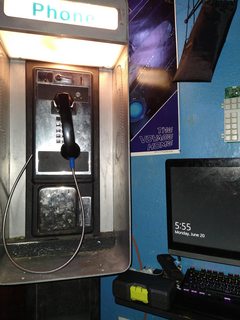
This is my payphone, I spent a couple months restoring it from the state it was in.
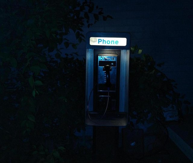
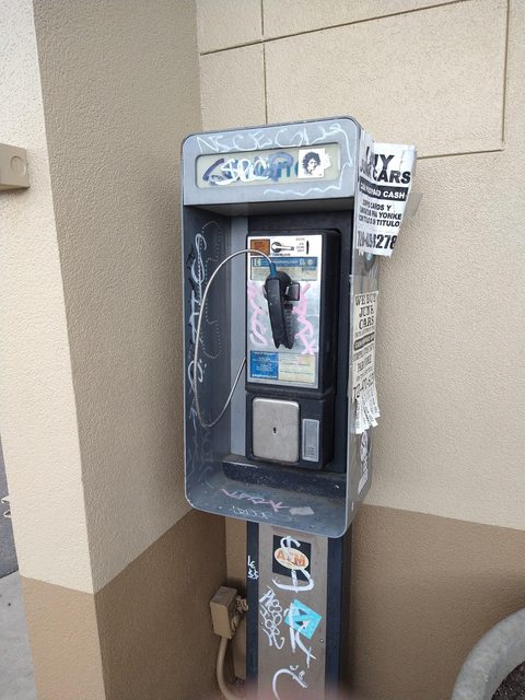
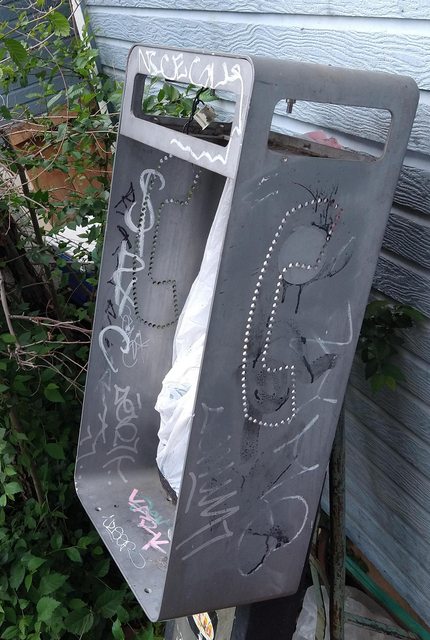
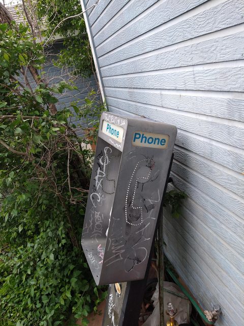
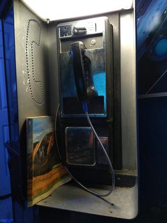
This was how I found it. Paid $50 for the whole thing which separately is worth several hundred dollars surprisingly enough. The frame is even rarer since you can't simply buy it anymore.
I was able to buy it for $50 under one condition. I had to remove it myself... So I took out my breaker bar, put a socket on it, and pulled the concrete bolts out, cut the wires free, and loaded it up into the jeep!
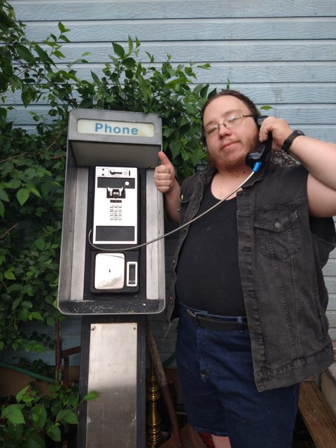
Here's me with the phone getting ready to move it to the back of the house to begin restoring it.
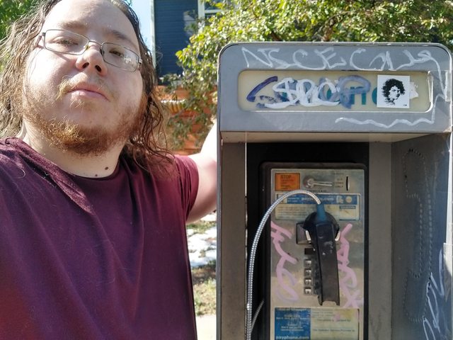
gods the thing had to weigh close to a hundred pounds but with a bit of patience and lifting with my legs I got it through the house and into the back to begin the cleaning and teardown.
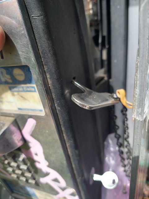
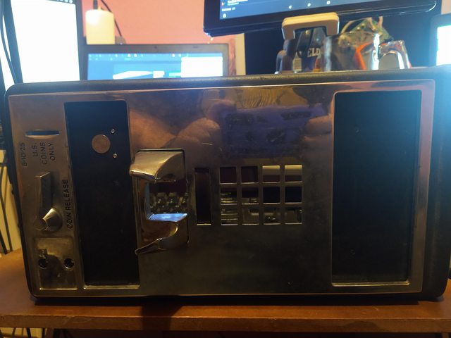
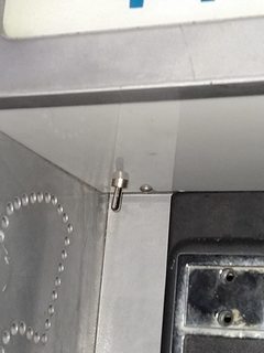
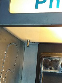
First I had to remove the front, fortunately it came with the keys!!!
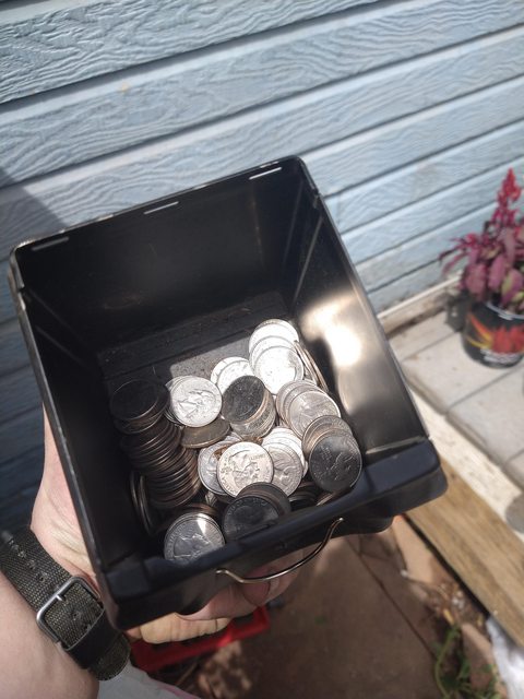
I also discovered thirty dollars in quarters in the coin box after managing to get that open so already a massive return on investment!
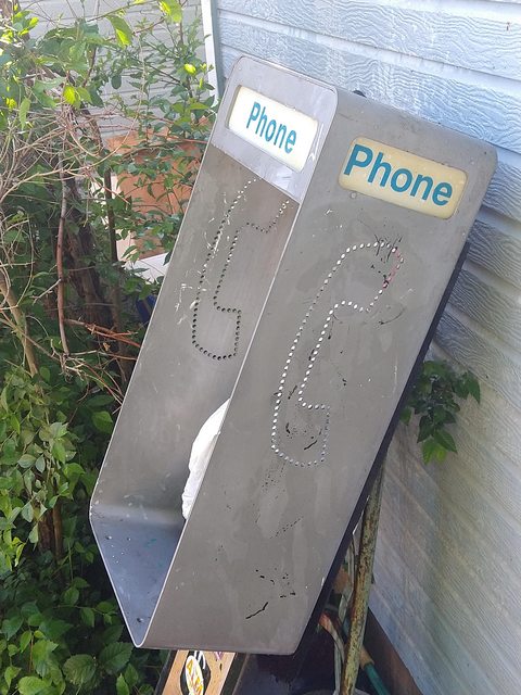
Anyway after a lot of cleaning and scrubbing I managed to get the grafitti off keeping one of the stickers that I like on there.
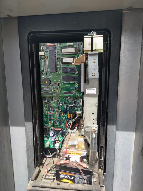
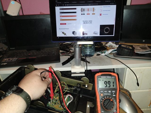
Next I had to work on the electronics side of things, I began by removing all of it from the frame and testing all the components with my multimeter.
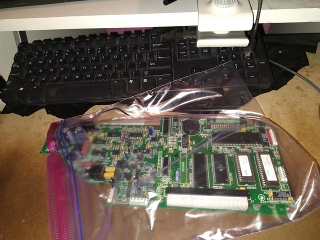
Fun fact, most smart payphones were using stuff like Zilog Z80 CPU's in them!!!
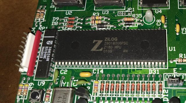
    anyway after having tested everything I realized... I had no way to reporgram it.  The process required a modem and despite having old hardware that was the one thing I didn't have... otherwise I'd have hooked it up to my XP/DOS computer and programmed it that way via the serial port.
    So giving up on that I discovered that I could get a new handset and phone board to convert it into a landline telephone from payphone.com.
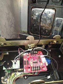
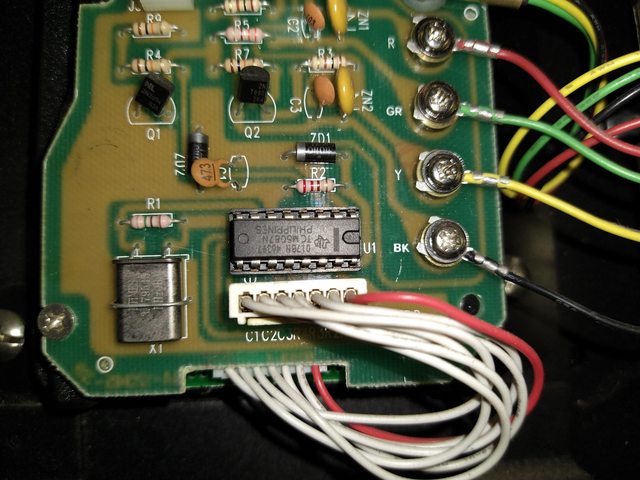
    I had one last hangup, the board had terrible grounding issues so I had to ground it to the chassis which was also grounded to the electrical outlet inside.  Oh! I forgot to mention.  the bottom of the pedestal houses an uprotected outlet so I took the time to replace it with one that had a proper cover and make a brand new power cable for it, fairly easy when you know what you're doing... and even put a proper sheath over it.
    After I'd done all that I realized it was missing something... when I took it apart I learned there was a CFL lamp inside the top and that the top part was supposed to light up.  Growing up I'd never seen a payphone light up, was this normal?  I had no idea so I went ahead and ran some new wire and replaced the CFL socket with a standard light bulb socket then stuck an LED bulb in there.  Why LED?  Less heat and power consumption for more light.
And now we're back to the image at the top, a fully cleaned up and working payphone... well almost, I had to stick an X-link POTS to bluetooth adapter in there but I had the power budget to spare... and a spare outlet :P It now sits at my workspace fully setup and working, and able to receive and send calls... from my cellphone, but also easily able to plug into a land line should I need it.
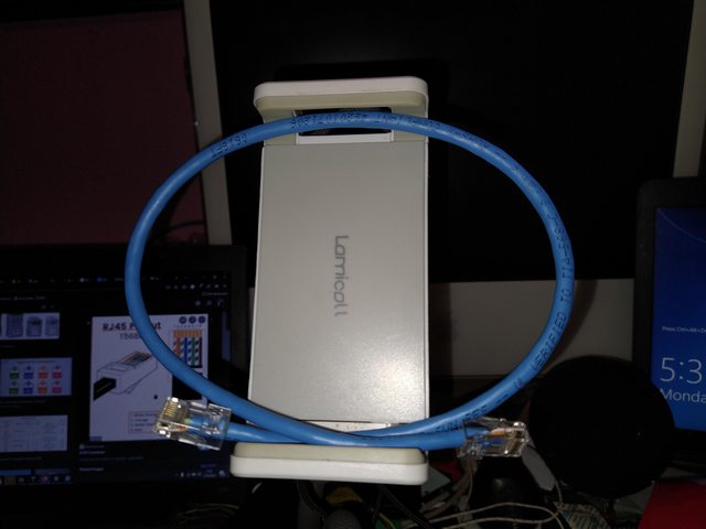
So almost everybody probably knows what a network cable is right?  Sorta looks like a phone cable but bigger with more pins?  Well there's more than one type of network cable, but the one most commonly used that everyone is familiar with is known as an RJ45 connector.  It looks like a phone cable because it's an 8 pin version of the RJ series connectors, the phone being a 6 pin RJ11/RJ12/RJ14 etc.  the RJ stands for Registered Jack.

When it comes to home networking these three are the most common from left to right you have RJ45 (ethernet), RJ11 (phone/modem), and BNC (coax)
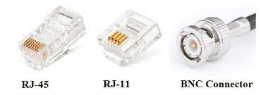
BNC looks a lot like your standard coaxial cable because the two are related except instead of sending video signals it sends network signals between two computers.  This was common in the 1980's.  From the 1990's onward most people used Rj45 or Ethernet cables.  and I'm going to go into how to make such a cable today.

You will need a few things first.
* | An RJ11/RJ45 Crimper | * |
* | A cable cutter/stripper | * |
* | some RJ45 Jack ends | * |
* | A spool or bundle of Ethernet cable. | * |
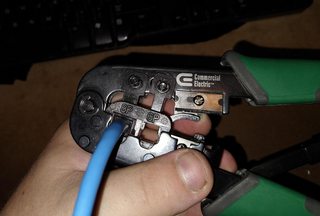
For our case we have a combination wire cutter, crimper, stripper, designed specifically for this purpose. Though just in case I keep some flush cutters as well since they make decent cuts but for the rest we use this tool by commercial electric.
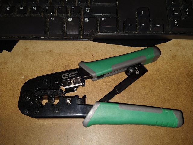
It's $10 at home depot and this plus a decent flush cutter and maybe a multi-tool is all you need to make network ethernet and phone cables.

next you'll want to be aware that cable uses different thicknesses.  Cat 5e can handle gigabit but it can be lossy, cat 6 is thicker and handles stuff better.
I ended up getting cat 6 cable and RJ45 jacks, cat 5 RJ45 jacks won't work with cat 6 cable due to it's thickness.
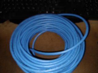
now measure your spool of wire to your desired length. give yourself some extra in case you need to re cut/strip the wire, a little extra is often common on custom cables and you can make it however long or short you want anyway.
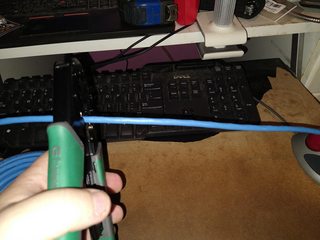
Once you have your cable measured and cut next you strip the cable.
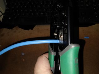
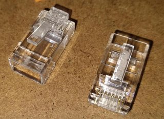
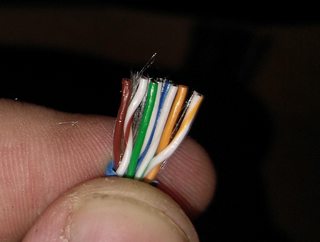
You want to strip about 1/2 to 3/4 of an inch of the outer sheath off revealing the 4 twisted pairs of wires.
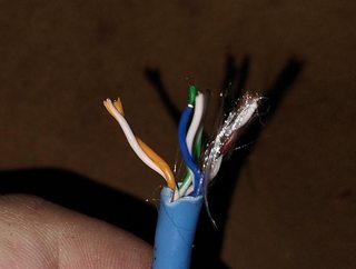
Next you untwist the wires and lay them out in the following order.
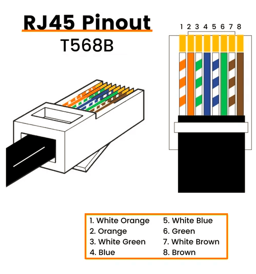
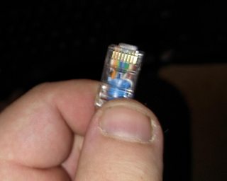
This is the guide I often reference when I can't quite remember the wire order. This next part is important, DO NOT STRIP THE INNER WIRES!!!! This is because the sheath on those wires actually helps guide them into the connector. basically you make sure the wires are flat in the correct order and then slide them into the connector, push them in as far as they will go. there's 8 channels that they'll slide into with pins at the end which poke into the wire ends.
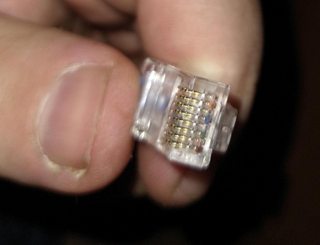
once you've checked your work and made sure the wires are all in there go ahead and stick the cable into the special slot on the crimper tool and squeeze, don't pull on the wire or they'll come loose and then you'll have to cut off the end and try again.
Then just repeat that process on the other side and you're done, you now have a network cable!
This process can take anywhere from 5 to 30 minutes depending on how good you are at it.  but it's worth it for two reasons.  First, because you know the cable was made correctly, it's not DOA from the factory.  And second, because if it ever breaks you left some extra on there right?  just cut off the damaged end and put another one on.  The end connectors are maybe $0.20 each and the cable is $20 for 100 feet of Cat 6 at the time of this writing.

Hopefully this tutorial was useful!  And as always, Knowledge is power, Use it wisely. - Zalost, out.
This here is the first console modding/hacking project I ever did, for a first try it was very difficult but it paid off and I ended up catching the modding bug afterward.
Here's the thing, the first Xbox was actually just a modified Linux PC (I know, weird right? microsoft made a linux based gaming console!)
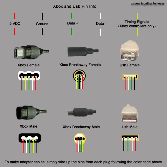
To that end the controller ports are actually Proprietary USB 1.1 ports, the only difference is an extra yellow wire which is for timing signals.
What you will need
* | Wire Strippers. | * |
* | Xbox controller dongle (that bit that plugs into the console with the round piece that connects to your controller) | * |
* | soldering iron (better to use than just twisting wires together... trust me) | * |
* | Electrical tape/Heat shrink cable sheath/tubing | * |
* | any old USB cable | * |
* | 10 minutes of your time. | * |
you can mod any section of cable, personally I prefer to modify the breakaway part of the controller cable because that basically functions as a PC adapter for any OG Xbox controller you want to use.
by the end of this project your cable should look something like this
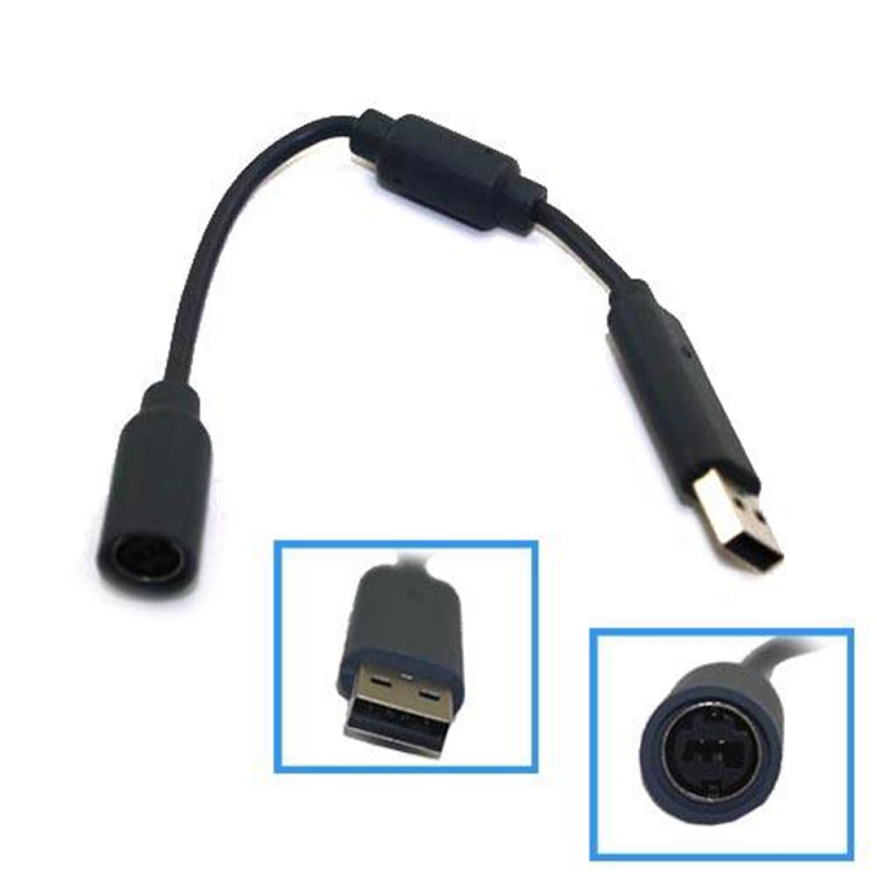
this is probably one of the easiest mods you can possibly do, you don't even really need schematics however I'm going to post them anyway because there are a lot of potential modders out there who haven't done anyhting with USB, though it really is as simple as matching the wire colors and connecting them together.
the next step in the process is to download the correct drivers for your Operating system.
If you have windows 8 or newer it will recognize your controller as an Xbox 360 controller so you shouldn't have any issues.
if you have an older version of windows which supports USB or another OS you will need special drivers.
Drivers for windows 98, 2000, xp, vista, 7
Believe it or not Linux has full support in it's generic Joystick drivers, and you can compile the linux drivers in OSX which is just plain awesome.
Furthermore you can utilize the Linux drivers in any Unix type environment with USB ports just as long as you have all the dependencies for the joystick driver, Just remember to calibrate your joystick before use.
as far as I know non Unix based and or windows based operating systems do not have an Xbox controller driver or if there is one it likely needs work.
now as for why you might want to connect a USB flash drive to an Xbox controller port... well if you happen to be into modding stuff you can use it as an alternative way to softmod your xbox by loading a hacked save file onto the flash drive and then loading that save file into the requisite game.
you can also use it to load full save files, back up your save files, and do all sorts of tricks like that to get the ball rolling.
that being said however I think I should post a separate deal for Xbox soft modding and all the pro's and con's that come with it.
Zalost - out
so here's my first real project to put on here, and probably one of my most challenging.
The Sega Genesis/Mega Drive Audio amp mod known as the mega amp.
To install it there's a few tricks but mostly just keep in mind, for a sega genesis model 2 you'll need an earlier revision rather than a later one, this is because sega replaced a lot of the barel cappacitors with surface mount ones and this makes it a real pain in the ole exhaust port.
Things you will need include...
* | A soldering iron | * |
* | Some desoldering braid | * |
* | A decent ammount of spare wire and or ribbon cable. | * |
* | A Mega Amp to install | * |
* | A #1 and or #2 Phillips Screw Driver (the one's with the plus shape on them) | * |
* | Patience | * |
* | Either a Circuit tester or a multi meter. | * |
You will need to follow the instructions listed here as this indicates what components to remove, then attach to the terminals closest to the lines shown in the image.
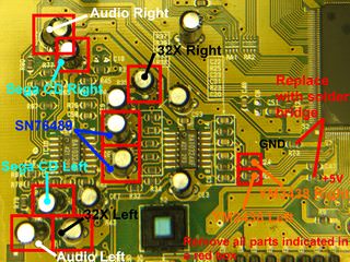
once you attach the wires then you need to attach their opposite ends to the labeled sections on the mega amp
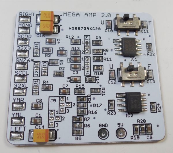
finally you have 2 options for the +5 volt and Ground wires, you can either attach them as indicated in the first image or you can attach them to the voltage regulator.
if you choose to do the latter there are 3 labeled pins on the board that you can solder to on the VR.
I O G, Input, Output, Ground.
attach 5V to Output, and ground to Ground.
that's pretty much it, but the sound quality is significantly better, and much clearer without any distortion, and that's with the filter turned off! so go ahead, give it a go and if you have the patience for it it's worth the install.
I'm going to keep this brief because while straight forward it's still fairly tedius.
you're going to need the following.
* | A joystick/gamepad/controller port of the type the console uses (either from a for parts console or from your own) | * |
* | A wiring diagram/pin layout for the controller... or a multimeter and time to work it out for yourself. | * |
* | A parallel port with Enhanced Capability mode (either via an add on PCI/PCI-E card or on your motherboard if it's an old system) | * |
* | A parallel port cable or connector of the right type to connect to your computer. | * |
* | Lots of spare wire. | * |
* | A soldering iron | * |
* | A hot glue (optional) | * |
* | Electrical tape and or heat shrink wire sheath. | * |
* | An electronics screwdriver kit (for removing connectors, opening cable covers, etc.) | * |
* | 7 1N4148 diodes (for genesis controller adapter, your parts type may vary depending on console and controller) | * |
Ok step one is to either reverse engineer your joystick or find a wiring diagram, for this tutorial I will use the wiring diagram for the sega genesis controller, this also works for ATARI 2600/5800/etc, commodore 64, and similar 9 pin trapazoid controller plugs on various consoles.
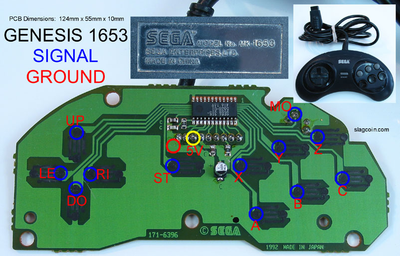
The thing to remember is that each of those traces goes to a pin on the connector for the controller, each button has a wire basically, and the parallel port will be interpreting that as data on multiple pins of said port and converting it to joystick inputs, this is very much old school but a good way to practice basic mods with little to no consequences.
Also remember there are 2 types of controllers, the 3 button and 6 button gamepads, the number of pins in use will vary but the layout should be the same regardless.
Also if you can find them... to save time on soldering and such look for DB9 and parallel port connectors like these.
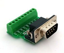
With those you just insert the wires and screw them in place removing the need to solder anything other than the diodes.
Step two is to wiring things up as shown in these schematics
Pins 3 through 9 are the diodes and all connect to DB9 pin 5. the rest should be attached as shown.
The colored pins are the one's you'll be using.
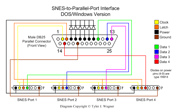
You'll also need a piece of software called PPJoy, this allows you to use the parallel port for joysticks and program them.
Follow this alternate pinout if you want to put 2 genesis controller ports instead of 1 on your adapter.
Just run the wires as shown, the triangles being the diodes connecting the appropriate number socket on the DB9 port/'s to the DB25 connector.
Do this correctly and install your driver and you should be able to just plug your joystick into the DB9 connector, run PPjoy and play whatever game.
Windows will read this as a generic USB controller so any game that supports this should work, alternately find one that converts this into an Xbox 360 controller type device like key 2 joy for games that support only that controller.
And that's all there really is to it, other controller adapters are similar, just be warned that this will take a few hours to do and patience is key!
Modify instructions to suit whatever controller you're adapting, so far the following works that I've tried.
Playstation Dual shock 1
Super Nintendo
Sega Gensis
Sega Saturn
Nintendo Entertainment system (NES)